Provides high-resolution ultrasonic measurements for accurate evaluation of casing and cement integrity
Tool Description
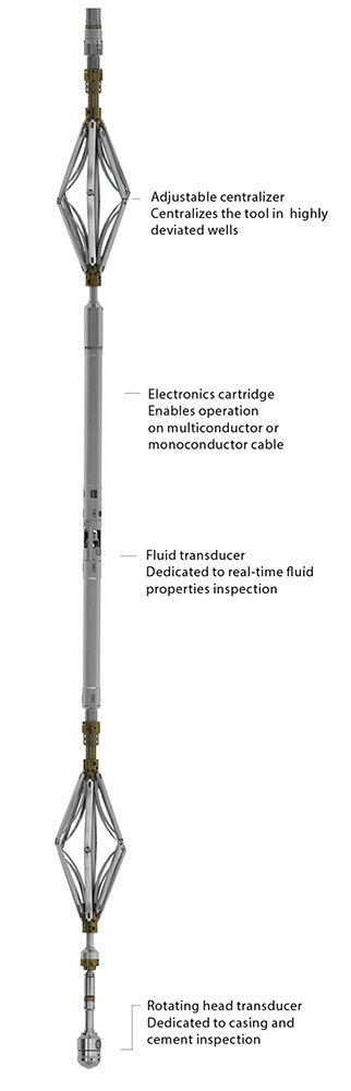
The Weatherford UltraView tool provides high-resolution data for accurate evaluation of cement, casing wear, casing thickness, corrosion imaging, and fluid properties. The tool uses two ultrasonic transducers. The primary transducer is dedicated to casing and cement inspection and is located in the rotating scanning head. This feature provides 360° circumferential coverage by capturing 72 samples per revolution.
The second transducer continuously measures borehole fluid properties and is located in the tool body. The fluid property measurements include real-time acoustic velocity, impedance, and density of the wellbore fluid.
The tool incorporates an advanced, high-speed, measure-on-position DC motor that rotates the primary measurement transducer. This transducer fires upon arriving at a precise point in its rotation, which ensures accurate circumferential depiction of casing defects and cement distribution.
Specifications
Measurement
Data | Acoustic impedance, fluid impedance, travel time, amplitude, casing ID, casing thickness |
Logging speed | 1,800 ft/hr (540 m/hr) |
Measurement range | Casing thickness: 0.200 to 0.800 in. (5 to 21 mm)* |
Vertical resolution | Cement evaluation mode: 1.0 in. at 1,800 ft/hr (540 m/hr)
Image mode: 0.5 in. at 1,800 ft/hr (540 m/hr) |
Thickness resolution | ±0.002 in. (0.051 mm) |
Acoustic impedance resolution | 0.2 Mrayl |
Accuracy | Internal radius: ±1% (FS)
Acoustic impedance: ± 0.5 Mrayl
Thickness: ±5% (FS) |
Depth of investigation | Thickness of casing; casing-to-cement interface |
Borehole fluids | Water-based fluids up to 15 lb/gal maximum mud weight**
Oil-based fluids up to 13.5 lb/gal maximum mud weight** |
* The second harmonic is used for thicknesses greater than 0.69 in. (18 mm).
** Maximum mud weights are for combined casing and cement evaluation and will be dependent upon casing and transducer characteristics. Some applications may be possible at higher mud weights under certain wellbore conditions.
Mechanical
Outer diameter | 3.38 in. (86.0 mm) |
Length | 18.66 ft (5.69 m) |
Weight | 315.00 lb (142.90 kg) |
Maximum temperature | 350°F (177°C)** |
Maximum pressure | 20,000 psi (138 MPa)** |
Minimum casing size | 4.5 in. (11.43 cm) |
Maximum casing size | 20.0 in. (50.8 cm) |
* Outer diameter depends on the scanning head used.
** Temperature and pressure ratings are 175°F (80°C) and 5,000 psi (35 MPa) when logging casing with an OD greater than 14 in.
Scanning Head*
Type | Diameter | Effective Radius |
A | 3.38 in. (8.59 cm) | 0.72 in. (1.83 cm) |
B | 3.13 in. (7.95 cm) | 1.28 in. (3.25 cm) |
C | 4.34 in. (11.02 cm) | 1.97 in. (5.00 cm) |
D | 5.44 in. (13.82 cm) | 2.56 in. (6.50 cm) |
E | 7.00 in. (17.78 cm) | 3.41 in. (8.66 cm) |
F | 8.71 in. (22.12 cm) | 4.25 in. (10.80 cm) |
G | 10.50 in. (26.67 cm) | 4.89 in. (12.40 cm) |
* Scanning heads are selected based on casing size and weight, transducer frequency, and the desired standoff distance between the transducer and inner casing wall.
Fluid
Transducer Frequency | Maximum Fluid Density |
Water-Based Fluids** | Oil-Based Fluids** |
250 kHz | 15.0 lb/gal (1,797 kg/m3) | 13.5 lb/gal (1,618 kg/m3) |
400 kHz | 13.8 lb/gal (1,654 kg/m3) | 11.5 lb/gal (1,378 kg/m3) |
600 kHz | 13.0 lb/gal (1,558 kg/m3) | 10.8 lb/gal (1,294 kg/m3) |
* Maximum mud weights are for combined cement and casing evaluation and will be dependent upon casing and transducer characteristics.
** Some applications may be possible at higher mud weights under certain wellbore conditions.